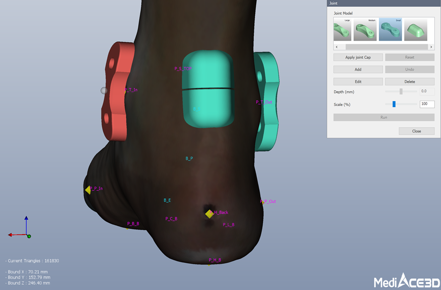
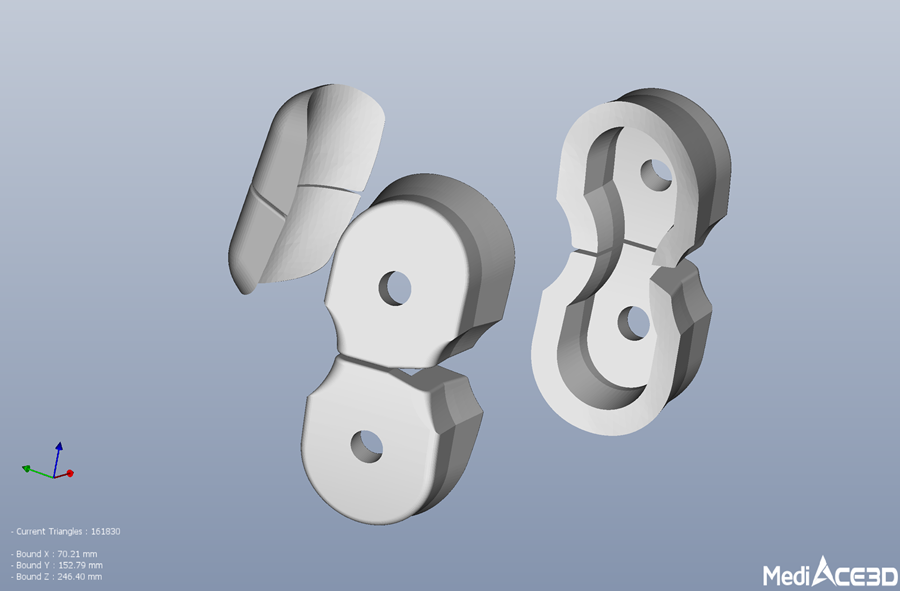
Select joint type for hinged AFO and add its object to the mesh model.
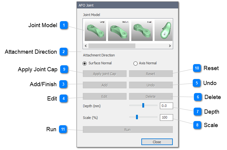
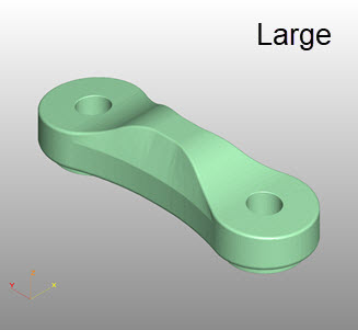
 Joint ModelSelect an joint part to add.
TAMARACK FLEXURE JOINT
|
Large
|
Medium
|
Pediatric
|
Stopper
|
|
|
|
|
|
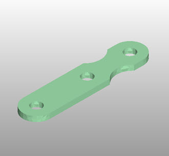
Plastic & Steel Joint
|
|
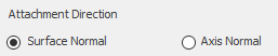
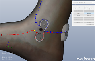
 Attachment DirectionSelect the attachment direction whether the joint model will attach along a surface or a fixed axis.
|
Surface Normal
|
Axis Normal
|
|
|
|
|
|
 Add/Finish
Start/End of adding joint parts after selecting an joint part.
|
|
 Edit
Edit added joint part. (It works after selecting the joint part)
After completing Add Finish, select the added part and click the Edit button to edit the selected part.
The selected accessory is displayed in brown color.
Apply modification such as move, rotation and change of depth in edit mode.
It is recommended that scale adjustments be applied only to the stopper model.
Move : Move the sphere shape in the center of the selected object with the right mouse button (move along the surface).
Rotate: Rotate with the mouse right button clicked on an object face another except the sphere shape on the selected object (rotate around the sphere)
|
|
 UndoCancel the last added part while adding the joint part in Add mode
|
|
 DeleteDelete the selected joint part.
After completing Add Finish, select the added joint and click the Delete button to remove the selected joint.
The selected joint is displayed in brown color.
|
|
 Depth
Adjust the position of depth by the slide bar In Edit mode
Adjust the depth value to adjust the position of the joint and the contact area of the stopper.
|
|
 Scale
Adjust the size of the selected stopper part.
Joint parts are used by assembling parts manufactured with fixed dimensions.
|
|
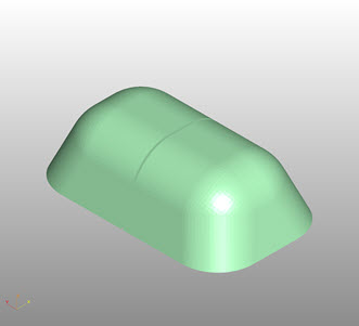
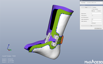
 Apply Joint CapApply the joint cap at the position of the joint.
Click the joint cap once to change the direction of the joint cap.
|
|
 ResetInitialize the applied joint cap
Change or reposition the joints and reapply the joint cap.
|
|
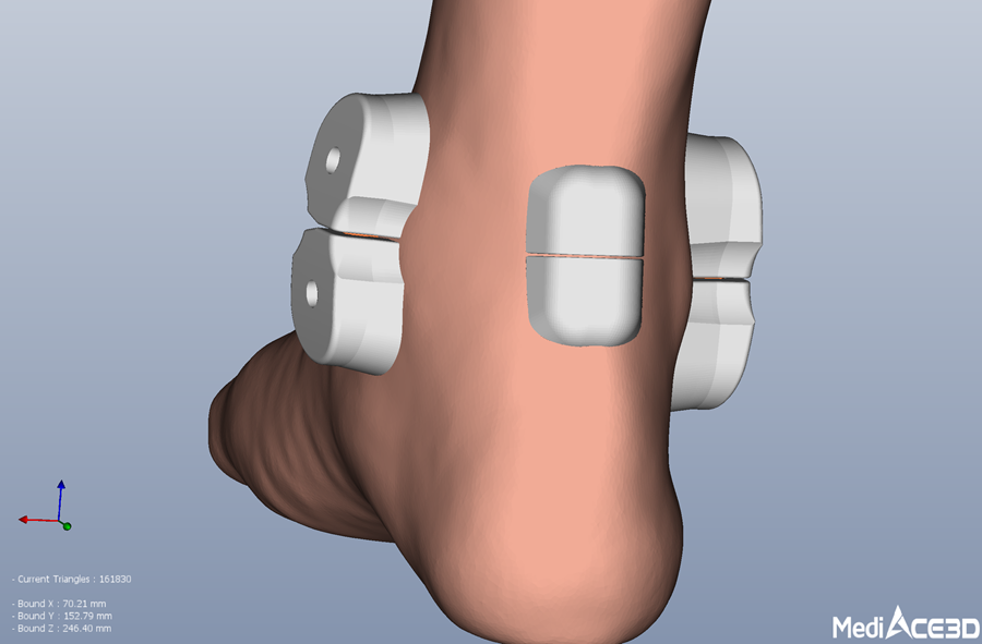
 RunCreate a joint cap object suitable for the AFO model by Boolean subtraction between the joint cap model and the foot model.
The dummy joint mesh model is created by adding subscripts such as _H0, _H1, etc. to project name and displayed in the project tree.
The Joint cap mesh model is created by adding subscripts such as _C0, _C1, etc. to the created joint model name and displayed in the project tree.
|
|
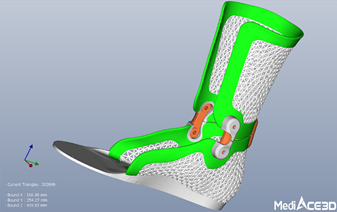
Brief images of Hinged AFO Design process